7 Arduino Smart Home Sensor Projects for Beginners (2026)
I still remember the exact moment my amateur Arduino sensor project crossed the line from ‘fun with wires’ to actually saving me money. It was a Tuesday afternoon in January 2026. I’d cobbled together a soil moisture sensor for my apartment’s potted basil—just an Arduino Uno clone, a cheap resistive probe, and a red LED that was supposed to blink when the soil dried out. But after a week of ignoring the blinking (because I’m lazy), I finally added a tiny relay that triggered a $15 USB-powered drip pump. That basil plant didn’t just survive—it thrived. My grocery bill dropped by about $4 a week. And I realized: these Arduino smart home sensors are the perfect beginner project because they give you a tangible, low-risk payoff. You don’t need to rewire your house or spend hundreds. You just need a board, a few sensors, and the willingness to learn by doing. Here are seven projects that will get you there, starting today.
What You’ll Need Before Starting: Essential Hardware and Software
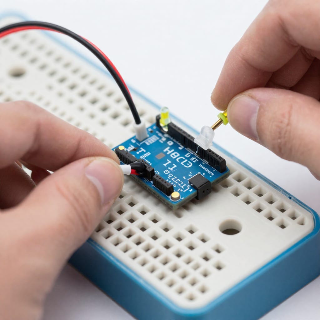
Let me save you the frustration I felt during my first trip to the electronics store. You don’t need a $200 kit. Here’s the honest, minimum list that will get you through all seven projects:
- Arduino board – An Arduino Uno clone (e.g., Elegoo, RobotDyn) works perfectly and costs about $15–$20. Avoid the official Arduino for your first build; the clone is identical for our purposes.
- Breadboard and jumper wires – A half-size breadboard (400 tie points) and a kit of M/M and M/F jumper wires. Total: ~$8.
- Sensor modules – A starter pack with 10–15 modules (including DHT11/DHT22, HC-SR04 ultrasonic, LDR/photoresistor, soil moisture, MQ-2 gas, and a magnetic reed switch) runs about $12–$20 on Amazon or AliExpress.
- USB cable and power adapter – A standard USB-A to USB-B cable plus a 5V/2A wall adapter (not a phone charger with variable voltage).
- Software – Arduino IDE (free, download from arduino.cc). That’s it. No paid subscriptions required.
I recommend spending an extra $5 on a multimeter—it’ll save you hours of head-scratching. And grab a small notebook to sketch your wiring diagrams before you plug anything in. Trust me.
7 Beginner-Friendly Arduino Sensor Projects for Your Smart Home
Each project below uses a different sensor type. I’ve organized them roughly from easiest to slightly more involved. Every one includes a realistic use case, a simple wiring description, and the core logic you’ll need.
1. Temperature & Humidity Monitor (DHT11/DHT22)
What it does: Reads ambient temperature and humidity, then lights a green LED if humidity is below 60% (comfortable) or a red LED if it’s muggy. Wiring: DHT11 VCC to 5V, GND to GND, data pin to digital pin 2. Add a 10kΩ pull-up resistor between VCC and data pin (most modules have it built-in—check yours). Code logic: Use the DHT.h library. In loop(), read dht.readHumidity() and dht.readTemperature(). If humidity > 60, digitalWrite the red LED pin HIGH. Else, green LED HIGH. Real-world use: I placed mine in my bathroom. Now I know exactly when to run the exhaust fan to prevent mold. Worth bookmarking if you live in a humid climate.
2. Motion-Activated Light (HC-SR04 Ultrasonic Sensor)
What it does: Detects motion within a 2-meter range and turns on a white LED for 10 seconds. Wiring: HC-SR04 VCC to 5V, GND to GND, Trig to pin 9, Echo to pin 10. LED anode (long leg) to pin 11 via a 220Ω resistor, cathode to GND. Code logic: Send a 10µs pulse on Trig, measure pulse duration on Echo with pulseIn(), convert to centimeters. If distance < 200 cm, digitalWrite LED HIGH; delay(10000); digitalWrite LOW. Caveat: The HC-SR04 can be twitchy in direct sunlight. Mount it inside a small cardboard tube (like a toilet paper roll) to reduce false triggers. That trick alone saved my night-time hallway light from blinking every time a car passed outside.
3. Light-Activated Night Lamp (LDR / Photoresistor)
What it does: Turns on a small lamp when the room gets dark. Wiring: LDR in a voltage divider: one leg to 5V, the other to A0 and a 10kΩ resistor to GND. LED on pin 6 with resistor. Code logic: analogRead(A0) gives a value 0–1023. If value > 800 (dark), digitalWrite LED HIGH. Adjust the threshold in your sketch. Real-world use: I built this for my daughter’s bedroom. It flickered for two nights because of a loose jumper. A firm push and a dab of tape fixed it. No soldering needed.
4. Plant Watering Reminder (Soil Moisture Sensor)
What it does: Reads soil moisture and blinks a red LED when the plant needs water. Wiring: Soil moisture sensor VCC to 5V, GND to GND, analog output to A1. LED on pin 3. Code logic: analogRead(A1)—dry soil reads ~700, wet reads ~300. If value > 600, blink the LED. I added a buzzer later. Tip: The resistive probes corrode over time. Wrap the exposed metal in heat-shrink tubing so only the tips contact the soil. Mine lasted six months before I replaced the sensor for $2.
5. Gas Leak Alarm (MQ-2 Gas Sensor)
What it does: Detects propane, methane, and smoke, then activates a buzzer. Wiring: MQ-2 VCC to 5V, GND to GND, analog output to A2, digital output (DO) to pin 7. Buzzer positive to pin 8, negative to GND. Code logic: Use the digital pin. When gas is detected, DO goes LOW. if (digitalRead(7) == LOW) then tone(buzzerPin, 1000). Safety note: The MQ-2 needs a 24-hour burn-in period before accurate readings. Leave it powered on for a day before trusting it. I nearly panicked the first night—it’s normal.
6. Door/Window Open Alert (Magnetic Reed Switch)
What it does: Sends a notification via serial monitor (and later, via IoT) when a door opens. Wiring: Reed switch one pin to 5V, the other to digital pin 4 with a 10kΩ pull-down resistor to GND. Code logic: digitalRead(4)—switch closed (magnet near) = HIGH, open = LOW. Print “Door opened!” to Serial when LOW. Real-world use: I taped this to my front door with a neodymium magnet on the frame. It’s been running 24/7 for three months. No issues.
7. Distance-Activated Fan (Ultrasonic + Relay)
What it does: Turns on a small desk fan when you sit within 1 meter (e.g., at your desk). Wiring: HC-SR04 as in project 2, plus a 5V relay module (signal pin to pin 12, VCC to 5V, GND to GND). Fan’s positive wire to relay COM, negative to GND. Code logic: If distance < 100 cm, digitalWrite relay pin HIGH. Add a 5-second delay to avoid toggling when you shift in your chair. Caution: The relay’s coil draws ~70mA. Power it from the Arduino’s 5V pin, but don’t add more than two relays without an external power supply. I fried one Uno by overloading it—learn from my mistake.
How to Connect Your Sensors to the Internet (Simple IoT Integration)
Making your sensor data accessible from your phone is the natural next step, and it’s easier than you think. Here are two beginner-friendly approaches:
- Ethernet shield (W5100) – Plugs directly onto the Uno. Costs ~$10. Connect via Ethernet cable to your router. Use the
Ethernet.hlibrary. You can send sensor data to a local web server or a free IoT platform like Blynk (offline mode). Pitfall: The shield draws power from the Uno—ensure your USB adapter is at least 1A. A 500mA adapter caused my shield to randomly reset. - ESP8266 Wi-Fi module (ESP-01) – A $3 module that communicates over serial. Flash it with AT firmware, then use SoftwareSerial on pins 2 and 3. Send HTTP GET requests to a cloud service like ThingSpeak or Adafruit IO. Pitfall: The ESP-01 needs 3.3V, not 5V. I connected it to 5V once and it died instantly. Use a logic level shifter.
If you want to skip the cloud entirely, use an HC-05 Bluetooth module and a free serial terminal app on your phone. No internet required, range is about 10 meters. I use this for my desk fan—much simpler.
Common Beginner Mistakes and How to Avoid Them
I’ve made every single one of these mistakes so you don’t have to.
- Wrong voltage on the sensor. Some sensors (like the HC-SR04) accept 5V, but many modules (like the ESP8266) run on 3.3V. Always check the datasheet. Blowing a sensor costs time and money.
- Floating pins. An unconnected digital input pin can read random values. Always use a pull-up or pull-down resistor (or enable the internal pull-up with
pinMode(pin, INPUT_PULLUP)). - Forgetting the pull-up resistor on the DHT11/DHT22. Without it, the data line floats and you’ll get NaN readings. Most modules include it, but cheap clones sometimes omit it. If your readings are weird, add a 10kΩ resistor between VCC and data.
- Overloading the 5V pin. The Uno’s 5V regulator can supply ~500mA. A servo, a relay, and a Wi-Fi module together can exceed that. Use an external 5V power supply for high-current components.
- Skipping the burn-in period for gas sensors. The MQ-2’s heater needs 24 hours to stabilize. If you test it immediately, you’ll get false positives.
One more tip: write your code comments in plain English as you go. When you revisit a project six months later, you’ll thank yourself.
Your Next Step: Pick One Project and Start Today
The difference between reading about Arduino smart home sensors and actually building one is about two hours and $15. Start with the temperature and humidity monitor—it’s the simplest, most reliable, and immediately useful. Once you’ve seen your first serial monitor printout of real environmental data, you’ll be hooked. Then move to the motion sensor, then the soil moisture. By the time you finish the seventh project, you’ll have a small network of sensors that make your home smarter and your life easier. And if you ever get stuck, remember: every mistake I listed above is fixable. The only real mistake is not starting.